Joystick Wiring Diagram

12 Volt 2 Way Switch Wiring Diagram, How to wire LED Lights & Use 2-Way switches | 12 Volt Planet, 7.8 MB, 05:41, 128,538, 12 Volt Planet TV, 2019-03-07T10:24:09.000000Z, 19, 12v Switch Wiring, www.chanish.org, 600 x 555, jpeg, 12vdc oznium volts dimmer chanish, 20, 12-volt-2-way-switch-wiring-diagram, Anime Arts
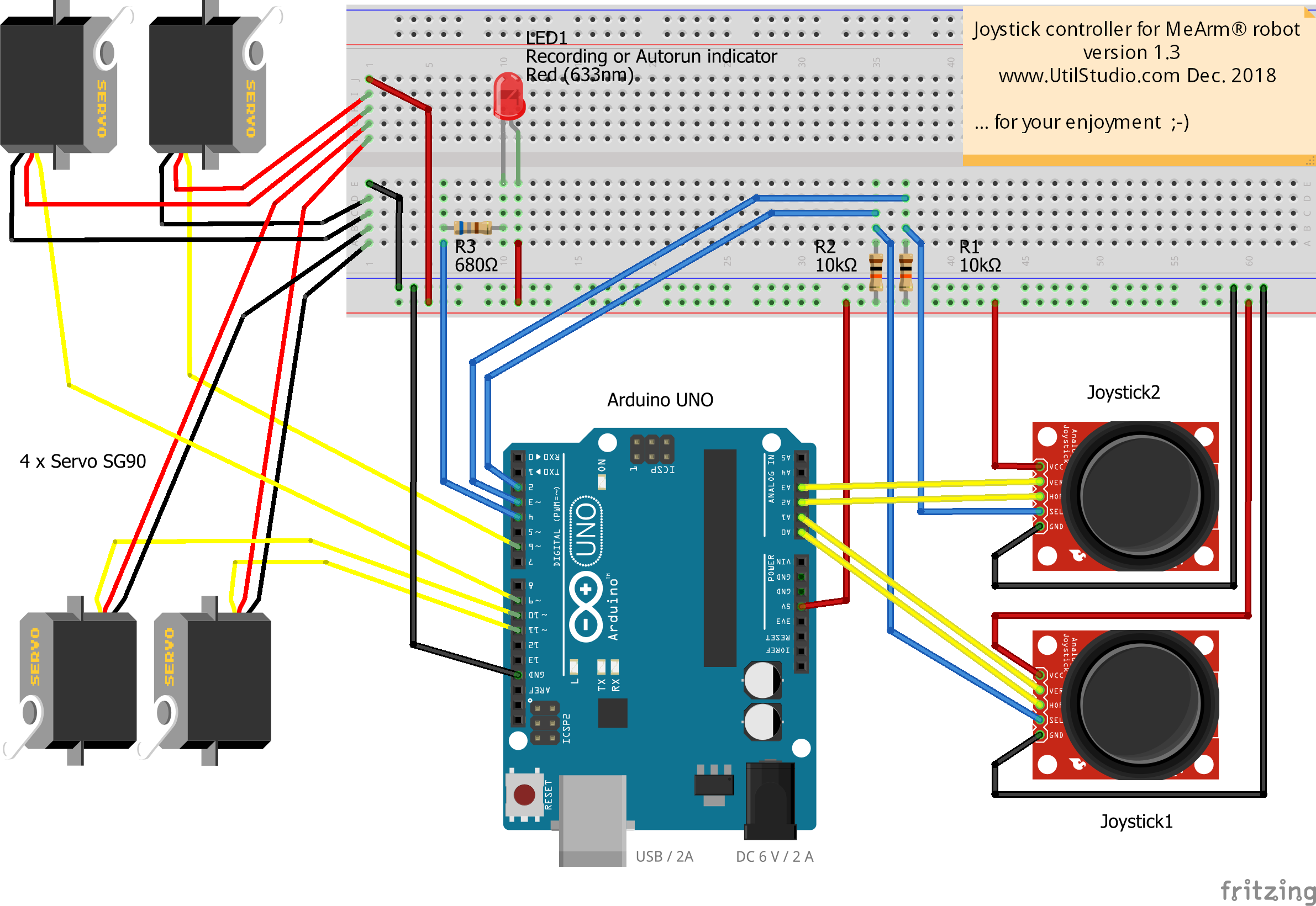
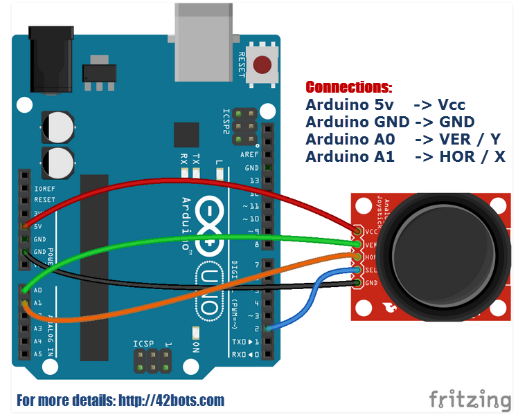
Pcb joystick controller gamecube arcade gc diagram buttons slagcoin wire wiring diagram1 diagrams analog replace using playstation. Joystick app www. pololu. com. Joystick potentiometer pololu wixel connecting. Connect the pins as follows, see the picture for a wiring diagram:
8 dkmh. pn. 580. b1. 02 • 520l0559 • rev a • 03/2003 electrical remote control levers technical information electrical remote control levers pvres accessories general pvres accessories meet the demand for simple installation, monitoring and safety. To work with an arduino joystick, you need to connect some wires to your arduino as the wiring diagram (figure 1) shows it. The gnd pin from the joystick needs to be connected to the ground (gnd). The +5v pin goes to the 5v pin of the arduino. Then, the vrx and vry pins go to two analog inputs and lastly, the sw pin connects to a digital input. Pc gameport (joystick) pinout. Nowadays the most common analogue joystick type is pc analogue joystick. This joystick model was presented by ibm together with their first ibm pc computer. The joystick is just a basic analogue joystick with two buttons.
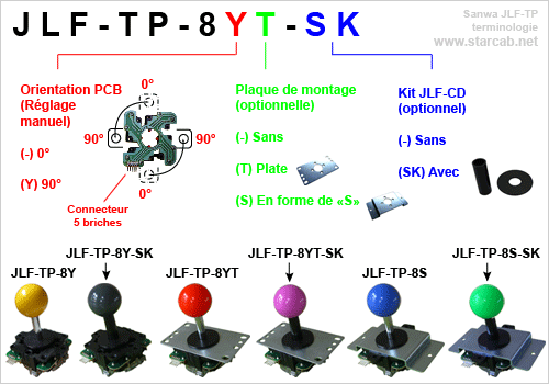
Sanwa Joystick Wiring Diagram

Joystick Connection | Spaulding International Cinema
Sainsmart Joystick Wiring Diagram - Complete Wiring Schemas

Sainsmart Joystick Wiring Diagram - Complete Wiring Schemas

Arduino Joystick Module Example – 42 Bots

Sanwa Joystick Wiring Diagram

Is there a wiring diagram for the "Thumb Joystick with select Button" - Help - DroneTrest
Mega Joystick Controller To Usb Wiring Diagram | USB Wiring Diagram

Usb Joystick Wiring Diagram | USB Wiring Diagram

Sanwa Joystick Wiring Diagram

